Monday, October 21, 2013

Class 7, Assignment 4: Sketchup Toolbar Series

SketchUp Toolbar Series


Selections:

It may be hard to tell but I have only selected the driveway in the above image.  I did this with a single click.

Left side: I dragged a selection box across the garage door and the fence on the right side of  the house.
Right Side:  I use the Shift-select command in order to pick and choose the objects I selected individually.

Components:


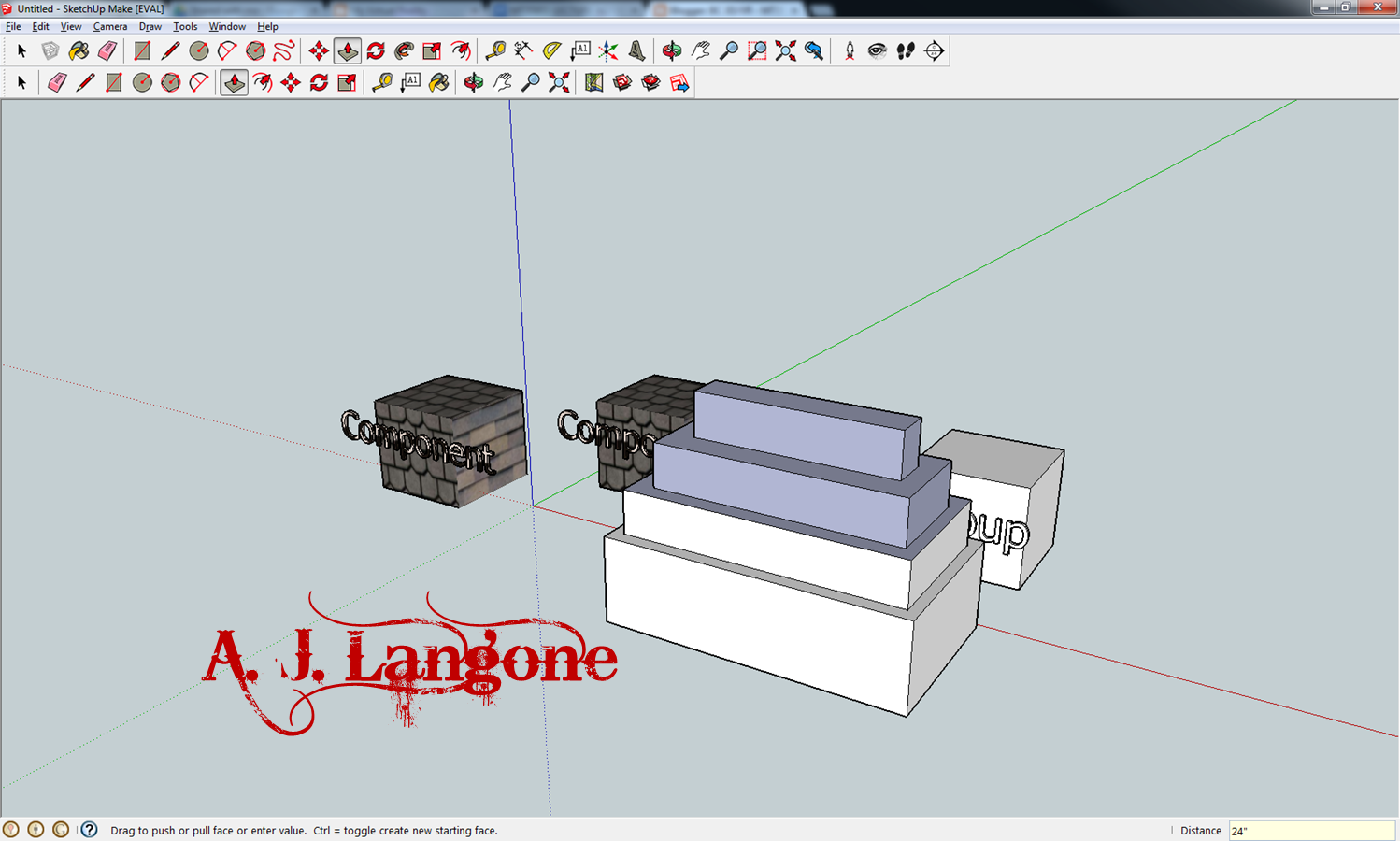
Here I've saved the left cube off as a component and the right cube as a group.  While it may seem to be just one shape, each cube is made up of edges, faces, and the 3D lettering.  

Left:  Experimenting with how component parts interact as one, in this case, rotating.
Right:  An example of how when a user is editing a component, the bounding box changes to a dotted line, indicating that individual pieces of the component can now be edited individually.

Paint Bucket:

Above are examples of using the paint bucket tool to customize components.  On the left I have used different materials to differentiate the cube from the text.  The right side depicts how by editing one component, the other copy inherited the same texture changes that I made to the original.

Eraser:

Using the Eraser tool along the edge of my cube removed sections of and "damaged" my cube shape.

Holding Shift while erasing the edges enables a technique called softening.  This allows a user to blend edges for a smoother look without destroying the overall shape.

Rectangle:

Examples of rectangles built on different planes are shown.  In the image on the right I have removed different rectangular sections from the original.

Lines:

Using the line tool to draw lines of different lengths freehand...

Creating a line set at 5m long and then subdividing it into even sections...

Circle/Polygon:

The above images show some uses of the circle and polygon tools.  When creating a circle or polygon you can determine the radius much like you can, the length of a rectangle or line.  Additionally, you can select the number of sides for your circle or polygon.  The image on the right shows how a 10 sided circle differs from a 10 sided polygon when the push/pull tool is applied.  

Arc:

Experimenting with the Arc tool.  The image on the right shows how a user is able to create Arcs that are tangent to two edges along different axes.  

These three Arcs were constructed by specifically designating the number of sides per Arc shape.  5, 3, and 7 respectively.  Arcs have a baseline of 12 sides by default.

Freehand:

Fun with the Freehand tool!  Due the the smart snap inherent in SketchUp, using the Freehand tool can be sort of clunky.  It is difficult to draw smooth lines.  Above you can see how I attempted to draw an eye and some contours into my original shape.  I erased some of the internal shapes for artistic effect. 

Move:

This is simply illustrating how the move tool also has a selection function built into it.

Here I am moving edges of grouped objects, warping their appearance.

Moving components along different axes.

Push Pull:

Using Push/Pull to establish set heights for the pieces of this shape - 5 feet at the top and descending by a foot each time thereafter.

Using Push/Pull to cut away and pull out sections of the original shape.

Rotate:

Using the Rotate tool to rotate the wings of this tie fighter individually.

Rotating both wings are once along a horizontal plane.


Follow-Me:

Using the Follow-Me tool to beveil the top edge of this shape.

Using the Follow-Me tool to create a lathe shape.  This required two perpendicular surfaces with a free hand design.  I then erased portions of the surface along the Y axis and related the Follow-Me tool to the X axis in order to create this shape.

Scale:

Uniform scaling of the object is shown.  One larger and one exactly 50% the size of the original.

Using the Scale tool to deform objects...

Offset:

Different application of the offset tool are shown.  On the right is an example of how you can repeat an offset into an adjoining shape by simply double clicking.  This technique created the double pane door effect.

Tape Measure:

While tough to see, if you look at the box shape you can see how I have initiated the Tape Measure tool from the upper left off to the lower right.  You can read the measurements in the lower right hand dialogue box.

Another use of the Tape Measure tool is to create construction guidelines to aid in building further shapes to appropriate scale and along the correct axes. 

Dimensioning:

Dimensioning is shown above.  It can be used to measure the length of an edge as well as the radius of a circle.  The dialogue box in the right image is how a user can customize the units, and visuals characteristics of dimensions within their work space.

Protractor:

Using the Protractor tool to measure angles and create construction guidelines.

Here I used the protractor to create a predetermined roof pitch and then dragged the roof up to meet the line.

Text & 3D Text:

Different text options are displayed.  You can affect setting that allow text to remain static regardless of your view orientation, as well use text that will reorient itself to accommodate your current view.

3D Text abuse...

Axes:

To change the location and orientation of axes within SketchUp only requires a few simple steps.  I imported an image for context.  The right image shows the axes in their original position.  The image on the left shows the new location and orientation that I set up.  This can be useful if a user is attempting to trace an image, such as a floor plan or similar sketch to aid in 3D construction.

Navigation:

Using the Orbit tool to view various angles of the model...

An example of using the middle mouse wheel to scroll into a very specific area of the model...

This is best way I could think to visualize the pan tool being used.  I'm simply panning across the same horizontal plane, using the model for context.

Position Camera/Look Around:

These four images are arrayed as such to illustrate the use of the Look Around tool.  When enabled you can reorient your view from a fixed point so as not to move around the 3D environment.

These angled shots were achieve using the Position Camera tool.  I simply chose locations within the environment and clicked.  I was zoomed to the location and the Look Around tool becomes automatically enabled at your new fixed position.

Walk:

This image show the walk tool being used.  The walk tool allows you to move around a 3D space at a fixed eye level.  It also sports a fancy collision detection system you can walk up stairs, through doors, and not clip into the environment.  I circled the indicator in red since it is difficult to spot in the image.

Sections:

In the upper left hand image you can see how I have hovered the Sections tool over the plane edge of the structure.  After clicking in that spot the result is the upper right image.  The lower images depict further hewing off of sections are various angles.  This is ideal for creating cutaway views of your model.

No comments:

Post a Comment